
Edge breaking is often treated as a simple deburring step, but when a drawing specifies a controlled edge radius, the requirement is closer to a dimensional process than a cleaning operation. The difference between a sharp, inconsistent edge and a repeatable 0.15 mm radius is rarely the cutting tool. It is the finishing method, the media selection, and how tightly the process variables are held from batch to batch.
For machined parts, consistent radius control matters because edges affect assembly, sealing, coating adhesion, stress distribution, and operator safety. A part that meets every dimensional tolerance can still be rejected because the edge condition is outside the envelope defined by the drawing note. Under ISO 13715, edges of undefined shape can be specified with symbolic indications that define allowable edge condition and size [1]. When the edge is controlled dimensionally, the notation is typically integrated into the geometric dimensioning and tolerancing scheme per ASME Y14.5 [2].
Why Edge Breaking Is a Process Control Problem
A burr can be removed without creating a controlled radius, and a radius can be generated without producing the same radius on every edge. That is the central challenge. Manual deburring reliably removes visible burrs, but it rarely produces a consistent radius because tool angle, hand pressure, and operator technique change throughout a shift.
Mass finishing approaches the edge differently. Instead of cutting only the burr, the workpiece moves through a media bed that contacts all exposed edges at once. The result is a radius that emerges from cumulative abrasion rather than from a single tool pass. This is why vibratory, centrifugal, and drag finishing are effective for edge breaking: they generate the radius progressively, and the process can be repeated when the media, load, speed, and compound are controlled.
The risk is that “progressive” can also mean “uncontrolled” if the process window is too wide. Edge radius consistency is not guaranteed by machine type alone. It is produced by understanding how much material removal is occurring, where it is occurring, and how those two factors shift as the media wears.
What Consistent Radius Control Actually Means
A consistent edge radius is not a single measured value. It is a distribution. A process may produce an average radius of 0.20 mm but still fail if one edge measures 0.08 mm and another measures 0.35 mm. For that reason, edge control should be defined the same way as other dimensional characteristics: target value, allowable variation, and measurement location.
The specification may come from an edge symbol on the drawing, a profile tolerance, or a general note such as “break all sharp edges R0.10–R0.25.” ISO 13715 provides the vocabulary and indication rules for these undefined edges [1]. When the edge has a functional role in assembly, ASME Y14.5 allows the requirement to be tied to datums and profile tolerance zones so the edge is controlled in relation to other features [2].
Surface texture is also part of the edge condition. The edge radius sits at the transition between two machined surfaces, and its finish affects how coatings wet the corner, how lubricant is retained, and how stress concentrates under load. Surface texture parameters and evaluation methods are defined in ASME B46.1 and ISO 21920-2 [3][4]. A controlled edge radius is therefore not only a geometry target; it is a combined geometry and surface finish requirement.
Methods for Edge Breaking and Radius Generation
The right method depends on part geometry, material, batch size, and how tight the edge tolerance must be.
Manual edge breaking is flexible and low in equipment cost, but it is the most difficult to validate for consistent radius control because the process relies on operator consistency. It is best reserved for very low volume or for touching up isolated edges before final finishing.
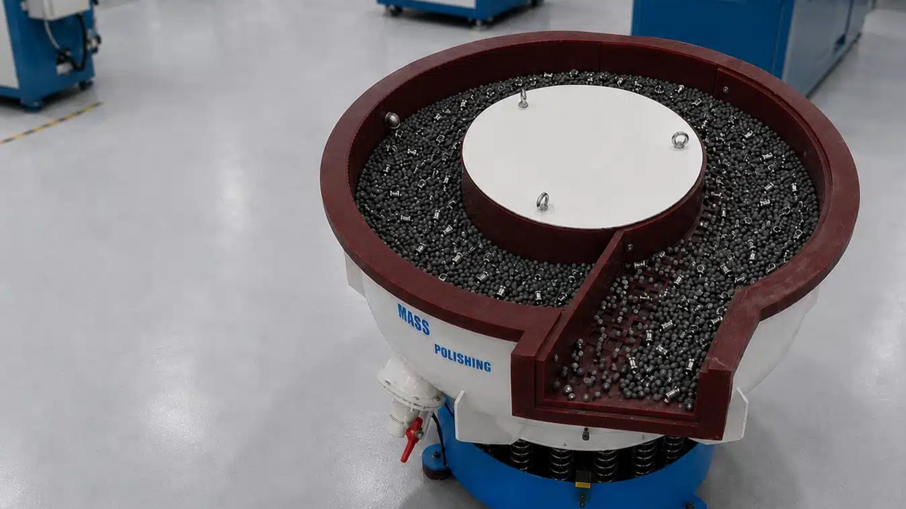
Vibratory finishing is a practical first choice for many machined parts. It deburrs, cleans, and smooths edges in bulk, and it can generate a controlled radius when ceramic or plastic media are matched to the material. Loading ratio, water flow, and compound concentration determine how uniformly the radius develops. Because the process is batch-based, part-to-part consistency within a batch is normally good when the load is well controlled.
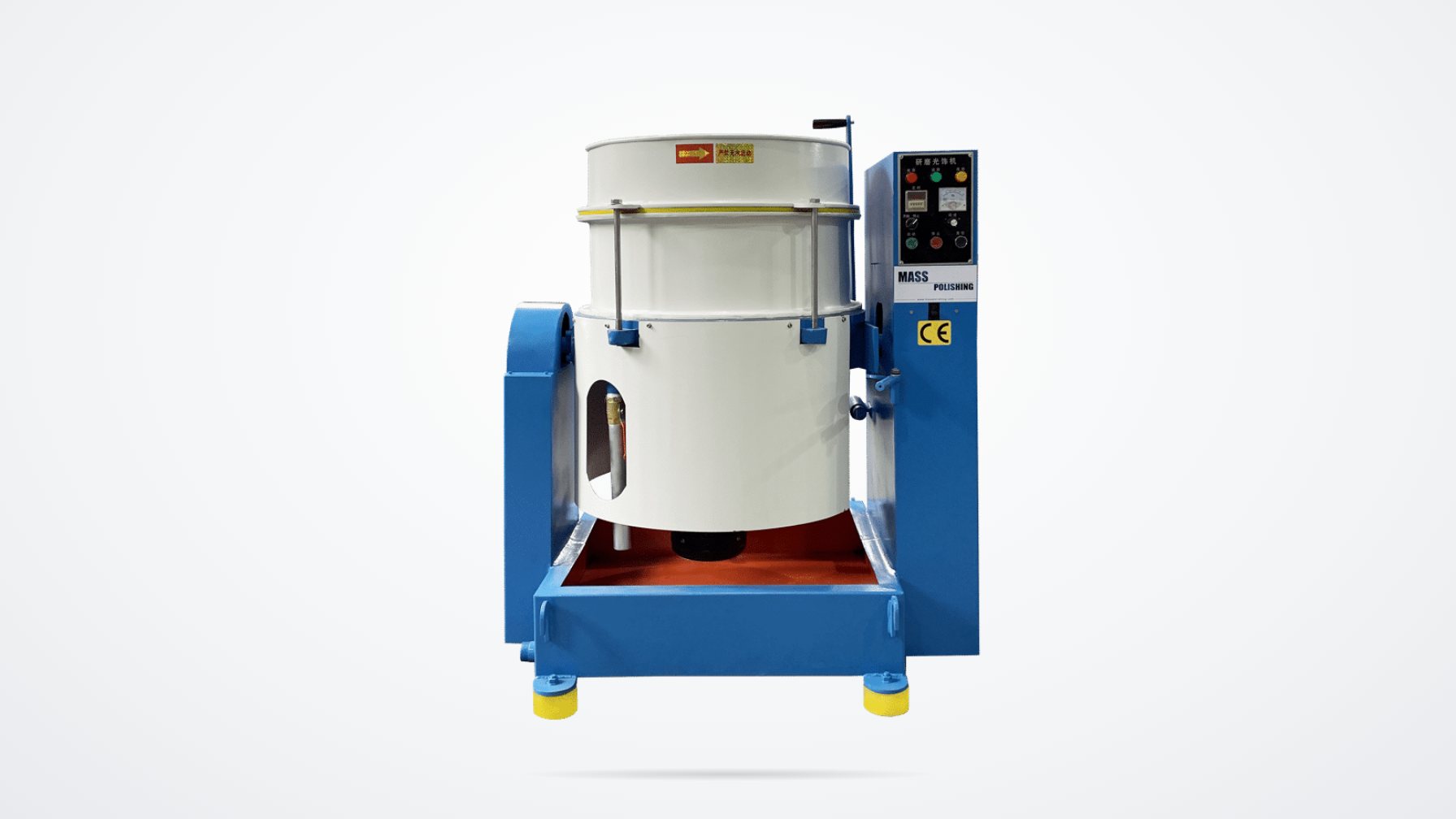
Centrifugal disc finishing applies higher energy than conventional vibratory finishing and is useful for tougher materials or parts that need faster edge development. The higher force reduces cycle time and can create a more distinct radius, but it also demands closer attention to media size so that holes and recesses are not over-finished.
Centrifugal barrel finishing offers high G-forces in a compact envelope and is well suited to small precision machined components. It produces rapid radius generation with good uniformity when barrels are loaded consistently.
Drag finishing clamps workpieces and drags them through a media bed. This protects edges that should not be contacted and allows selective edge treatment. It is the preferred method when the part has critical tolerances, fine details, or a requirement to preserve sharp adjacent features while breaking selected edges.
Key Process Variables for Repeatable Edge Radius
Edge radius is not a machine setting; it is the outcome of several interacting variables. The four that have the greatest effect on repeatability are media condition, load geometry, time, and fluid management.
Media shape and size determine where contact occurs. Large, aggressive ceramic shapes cut quickly and produce a broader radius, while smaller or finer media refine the radius and improve surface finish. If the media is too large for holes or slots, it may not reach internal edges or may lodge in the part. If it is too small, edge development slows and the process becomes finish-dominated rather than radius-dominated.
Loading ratio and part orientation control how much energy reaches each edge. An overcrowded bowl slows media movement and produces uneven contact. Too low a load increases part-on-part contact and can cause nicks or excessive edge rounding on exposed surfaces. The same principle applies to centrifugal disc and barrel systems, where chamber fill level and weight distribution must be repeated for every cycle.
Cycle time is the most visible variable, but it is only reliable when the other inputs are stable. A 30-minute cycle that produces R0.15 today will not produce the same radius next week if the media has worn, the compound concentration has drifted, or the incoming burr condition has changed. Time should be treated as a final trim variable, not as the primary control mechanism.
Water and compound flow affect cutting speed, cleaning, and foam generation. Poor wetting reduces abrasive action, while excessive water can dilute the compound and slow the process. Stable flow is essential for a repeatable edge radius, especially in high-volume finishing cells.
Machine – High Energy Deburring)
Getting a stable edge radius depends on repeatable load, water, and compound control. <How to Use Vibratory Finishing Machine> covers operating parameters and daily setup routines.
When radius variation appears only on some edges, the cause is usually equipment condition, media loading, or compound flow. <Common Problems and Countermeasures of Polishing Machine Equipment> covers troubleshooting for vibratory and disc finishing lines.
Pre-finishing surface condition directly affects how uniformly an edge radius develops. <Why Should the Surface of Metal Products Be Smoothed> covers the link between surface preparation and final finish.
Equipment and Media Selection for Uniform Edge Radius
The selection process should start with the part, not the machine. Key inputs include material hardness, edge length, part size, holes or slots that must be protected, and the required radius tolerance.
For general machined parts in mixed production, Vibratory Finishing machines with straight or curved wall bowls provide an economical and flexible platform. Models with separation systems simplify media recovery and reduce manual handling, which improves batch-to-batch consistency. When the edge radius must be generated faster or the material is harder, Centrifugal Disc Finishing is a better fit because the higher energy shortens the time to reach the target radius.
For small precision components such as hydraulic fittings, aerospace fasteners, and medical instrument parts, Centrifugal Barrel Finishing delivers high energy in a smaller footprint. Where selective edge treatment is required, Drag Finishing allows the part to be fixtured so that only selected edges are exposed to the media.
Media selection follows material and geometry. Ceramic media is the workhorse for steel, stainless steel, titanium, and other hard alloys because it combines cutting action with long life. Plastic media is more suitable for aluminum, brass, zinc, and other soft non-ferrous metals where edge radius control must be achieved without excessive stock removal. Steel burnishing media refines and brightens after the radius has been established, while walnut shell or other dry media can be used for delicate parts that require only a light edge break.
Compound choice supports the mechanical process. A general-purpose liquid compound cleans and assists cutting, while polishing compounds brighten the surface after edge development. Corrosion protection is important for ferrous parts, especially when the finishing line feeds a subsequent coating or assembly operation.
Validating Edge Radius in Pilot and Production
The only reliable way to prove consistent radius control is through a structured pilot run. Start with representative parts that reflect normal incoming burr variation, not only clean, easy samples. Define the accepted range, select a measurement method, and record data from multiple locations on each part.
– Parts Separation Process)
Typical validation steps include measuring incoming edge condition, documenting the exact media lot and load weight, running several cycles across a range of target times, and comparing the resulting radius values with the specification. Optical comparators, profile projectors, or stylus surface measurement systems can be used depending on the tolerance and part access. The data should show not only that the average radius meets the target, but that the variation is small enough for the full tolerance band.
A common mistake is to validate one machine and then duplicate the process on another machine without adjustment. Even identical models can perform differently if media is at a different stage of wear or if the loading method is not standardized. For production transfer, the pilot result should include the full machine settings, media specification, compound flow rate, and inspection method so the process can be reproduced.
When the edge radius is critical, long-term control is better maintained by periodic check parts and media refresh than by waiting for a dimensional failure. Mature processes use a combination of incoming part checks, cycle-time monitoring, and final radius sampling to hold the process window stable.
Process development support. If the goal is a specified edge radius across a new machined component family, the strongest starting point is a controlled sample run. Email [email protected] with part drawings, material, required edge radius, and batch volume. The evaluation should include machine type, media class, cycle target, and measurement results so that production parameters are based on data rather than guesswork.
Common Edge Consistency Problems and Fixes
Radius develops too slowly. The media may be too fine, the charge may be too light, or the compound concentration may be too low. Increasing media aggressiveness or energy input is more effective than simply doubling cycle time.
Some edges round more than others. This is usually a contact problem. The part may be nesting, shielding certain edges from media flow, or the load may be too dense. Changing load level, adding dividers, or selecting a different media shape can restore uniformity.
Holes and slots become over-finished. Media may be too small and penetrating recesses aggressively. A larger media shape or a fixtured drag finishing process can limit contact to the required edges.
Part-on-part contact creates nicks. Increase the media-to-parts ratio, reduce parts per batch, or use machine dividers for delicate parts. The objective is to ensure parts travel through the media bed without contacting one another.
Radius is consistent but surface finish varies. Media wear is often the cause. As edges wear, the finish can shift from cutting to burnishing. Media replenishment and periodic roughness checks prevent drift.
The same setting produces different results between operators. Standardize the entire loading and fluid sequence. Write the setup as a repeatable procedure, including media level, water flow, compound dosing, and separation settings.
Request a Verified Edge Breaking Process
A controlled edge radius is easiest to hold when the process is developed around the actual part rather than copied from a general guideline. Mass Polishing provides sample processing and process development that starts with your part, material, and drawing requirement, then builds the machine-media-compound combination needed to reach the target radius consistently.
Email [email protected] with your part drawings, material grade, target edge radius, and expected monthly volume. The evaluation should include a pilot run report with measured edge values and recommended production settings.
Frequently Asked Questions
What is the difference between deburring and edge breaking?
Deburring removes loose or protruding material from a machined edge. Edge breaking goes further by producing a defined radius or chamfer along that edge. Deburring is often a cleanliness requirement, while edge breaking is frequently a dimensional or functional requirement.
Can vibratory finishing hold a tight edge radius tolerance?
It can, provided the process is characterized and controlled. Vibratory finishing generates radius through media contact, so media type, load ratio, compound flow, and cycle time must be held within a validated window. For very tight tolerances, centrifugal disc or drag finishing may be more suitable because they offer higher energy or selective contact.
How do I prevent small holes from being rounded too much during edge breaking?
Use media that is large enough to avoid deep penetration into holes, reduce the energy or cycle time, or switch to a fixtured drag finishing process that contacts only selected edges. Part geometry and hole size should guide media selection before the pilot run.
What edge radius can mass finishing achieve on machined steel parts?
The achievable radius depends on material, starting edge condition, media, and process time. Mass finishing can produce a range from a light edge break to a clearly defined radius, but the specific value must be validated on the actual part. A pilot run is the only reliable way to establish the achievable window.
How often should media be checked for consistent edge radius?
Media should be inspected as part of the production routine. Wear directly changes edge development and surface finish, so media level and shape should be recorded at regular intervals and replenished before the process drifts outside the validated window.
References
[1] International Organization for Standardization. ISO 13715:2017, Technical product documentation — Edges of undefined shape — Vocabulary and indications. ISO, Geneva, 2017.
[2] American Society of Mechanical Engineers. ASME Y14.5-2018, Dimensioning and Tolerancing (GD&T). ASME, New York, 2018.
[3] American Society of Mechanical Engineers. ASME B46.1-2019, Surface Texture (Surface Roughness, Waviness, and Lay). ASME, New York, 2019.
[4] International Organization for Standardization. ISO 21920-2:2021, Geometrical product specifications (GPS) — Surface texture: Profile method — Part 2: Terms, definitions and surface texture parameters. ISO, Geneva, 2021.
If you’re interested, check out these related articles:
Jewelry Industry
How to Choose the Abrasive of Vibration Grinder
Operation Mode of Drum Grinder