
Jet engine component surface treatment is not one process. A compressor blade, a turbine disc and a fan casing reach the finishing stage with different geometry, different allowable stock removal and different functional requirements, and a process that suits one can ruin another. What decides the result is the sequence: media, compound, contact pressure, and the measurement method agreed before the first part runs. Most of the difficulty in aerospace finishing sits in that specification work rather than in the machine itself. What follows covers how each component family is finished, where the real limits sit, and what to settle before a trial produces a number worth quoting.
What the Surface Has to Do Before It Looks Right
A polished blade is not the objective. Surfaces on engine hardware are finished because three functions depend on them.
Fatigue life depends on the absence of sharp edges, folded metal and deep machining marks, all of which concentrate stress. Flow performance depends on airfoil roughness and on edge geometry the finishing step either preserves or destroys. Coating, bonding and sealing depend on a clean substrate with the right texture. These requirements can pull against each other. A process that brightens an airfoil by removing more stock can also open the trailing edge past its drawing limit, while a process that leaves a fine non-directional texture for coating adhesion may look worse than a neighbouring part that was never meant to be functional.
The paperwork that travels with aerospace work is often read as proof of the surface. It is not, and the gap between the two causes most disputes.
| Record | What it establishes | What it does not establish |
|---|---|---|
| AS9100D certificate [1] | the supplier’s quality management system conforms to the aerospace standard | that a specific lot meets your drawing |
| Nadcap accreditation [2] | the accredited process scope has been audited | approval of your alloy, geometry or acceptance limits |
| Ra value reported to ISO 21920-2 [3] | a profile parameter was determined under a stated method | that the cutoff, evaluation length and measurement location match your requirement |
| AMS 2430 peening specification [4] | how automatic shot peening is controlled and verified | a finishing recipe, or permission to remove the peened layer afterwards |
| Photograph of a finished blade | general appearance | edge radius, media embedment or subsurface condition |
Read that table from the middle column outward. A quality certificate answers a system question. A parameter report answers a measurement question. Only an acceptance record tied to the drawing answers the question the design authority actually asked, and it is agreed before production rather than after.
The parameter itself needs the same care. Ra is an arithmetic mean over an evaluation length, so two surfaces can report the same value and behave differently when the cutoff or the trace direction changes [3]. A surface that is rough across the lay and smooth along it will give different numbers depending on which way the stylus runs. A drawing should therefore name the parameter, the cutoff and the direction, not just a figure.
Blades, Discs and Casings Need Different Finishing Approaches
Process selection starts from what the part cannot tolerate. A blade has a thin airfoil and two edges that carry aerodynamic and fatigue function. A disc has substantial mass but slots, holes and faces where a burr becomes a crack starter. A casing has a large thin wall, bores that must stay round and flanges that must stay flat.
| Component family | What the process must not do | Process family that usually fits | Main control point |
|---|---|---|---|
| Compressor and turbine blades | round the trailing edge, chip the tip or lose the root contact face | drag finishing with fixtures, or high-energy barrel finishing | edge radius and fixture support |
| Turbine and compressor discs | remove the peened layer, distort a thin web or round a slot root | barrel finishing, drag finishing where slot edges need a set radius | position in the process sequence |
| Fan and compressor casings | distort the wall, trap compound in bores and blind holes | large bowl or trough vibratory machines at low amplitude | support, rinse and dry |
| Bushes, fasteners and fittings | lose thread form or hold media in cross holes | centrifugal disc or magnetic finishing | media size against feature size |
Two of these families can share a machine type and still need separate recipes, and none of them should share a media charge between alloys without a cleaning procedure.
Energy level is the first lever. A centrifugal barrel machine drives media against the work at high force and shortens cycles, while a vibratory bowl moves the mass more gently and holds geometry with less risk. A drag finisher takes a third route: the part is clamped in a holder and pulled through the media, so contact pressure and angle of attack are set by the fixture rather than by the load. Which of the three fits is decided by the tightest geometric limit on the part, not by the throughput target.
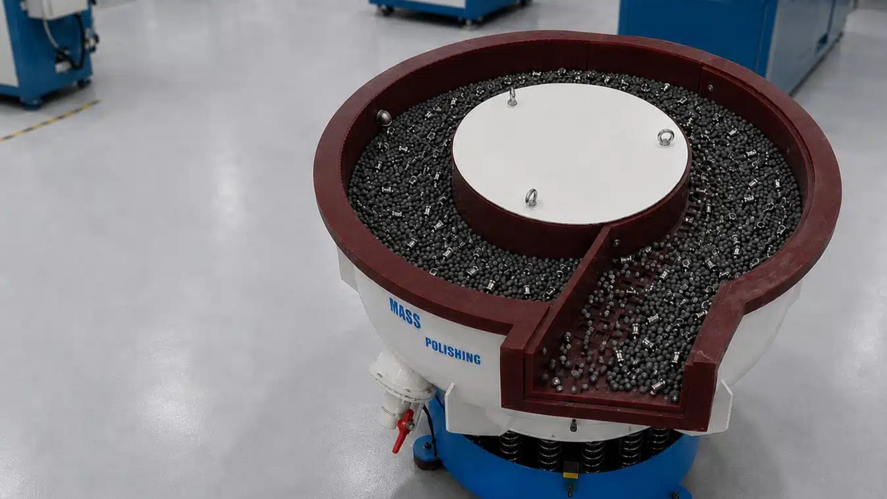
The choice between a high-energy barrel process and a bowl process is usually settled on cycle time and edge control rather than on machine footprint. <Vibratory Finishing vs Centrifugal Barrel Finishing> covers how the two methods differ in finishing intensity and media action.
Where Edge Control Decides the Result on Blades
Blades fail a finishing specification in three places: the trailing edge, the tip and the root.
The trailing edge is the thinnest feature on most airfoils. Media that is too coarse or too heavy rolls it, waves it or breaks it off in small chips. Smaller media follows the airfoil contour more closely but lengthens the cycle, and the cycle has to stay short enough that the leading edge does not lose radius while the operator waits for the trailing edge to clean up. The tip has the same problem in a smaller area. The root is the opposite case: the dovetail or fir-tree contact faces are functional surfaces that must stay flat within tolerance, so only the outer edges may be broken. Anything that treats the root face as just another surface has already lost control of the part.
Fixturing is how that separation is achieved. Drag finishing holds each blade individually, so a contact face can be masked or kept out of the media stream while the airfoil and the root edges are worked. Barrel finishing cannot isolate one face, which makes it suitable for blades where the whole surface is to be treated uniformly and unsuitable where a contact face must be preserved.
Cooling holes and internal passages need a decision recorded on the drawing, not left to the operator. Media that enters a passage may not come out, and small pins or fine media can lodge at a hole edge. Whether hole edges are treated, masked or inspected afterwards changes both the fixture and the acceptance check.
Measurement closes the loop. A radius gauge is a screen: it tells an operator the edge looks like one of a family of shapes, and it produces no number. A profile trace across the edge, or an optical method agreed with the customer, produces the value the drawing can accept. Which of the two is used should be fixed before the first part, because an edge that passes one method can fail the other.
The Sequence Matters More Than the Finish on Discs
On a disc, the surface finish is the easier half of the problem.
Fir-tree slots are broached, which leaves sharp corners at the slot root and burrs at the slot exit. A burr sitting at the root is a stress raiser in the most heavily loaded region of the part, so deburring has to be written as a radius with a tolerance and a measurement method, not as the removal of visible metal. Bolt holes and balance holes follow the same logic, with an added risk: a raised lip around a hole changes how the face clamps and how the disc sits in the fixture.
Sequence decides whether the finishing step helps or harms. If peening follows finishing, the compressive layer is applied to the surface the finishing step produced, and folded metal left behind is covered rather than removed. If finishing follows peening, the abrasive action removes part of the layer that was just created. AMS 2430 controls how automatic peening is set and verified [4]; it does not authorise a later mechanical operation on the peened surface. Where a drawing genuinely requires a touch-up after peening, the engineering authority sets the limit and the verification, and that decision belongs on the drawing.
Distortion is the second constraint. A thin web or a large diameter disc can move under high-energy barrel action, so support, load pattern and energy level all need checking, and flatness should be measured after the cycle rather than assumed.
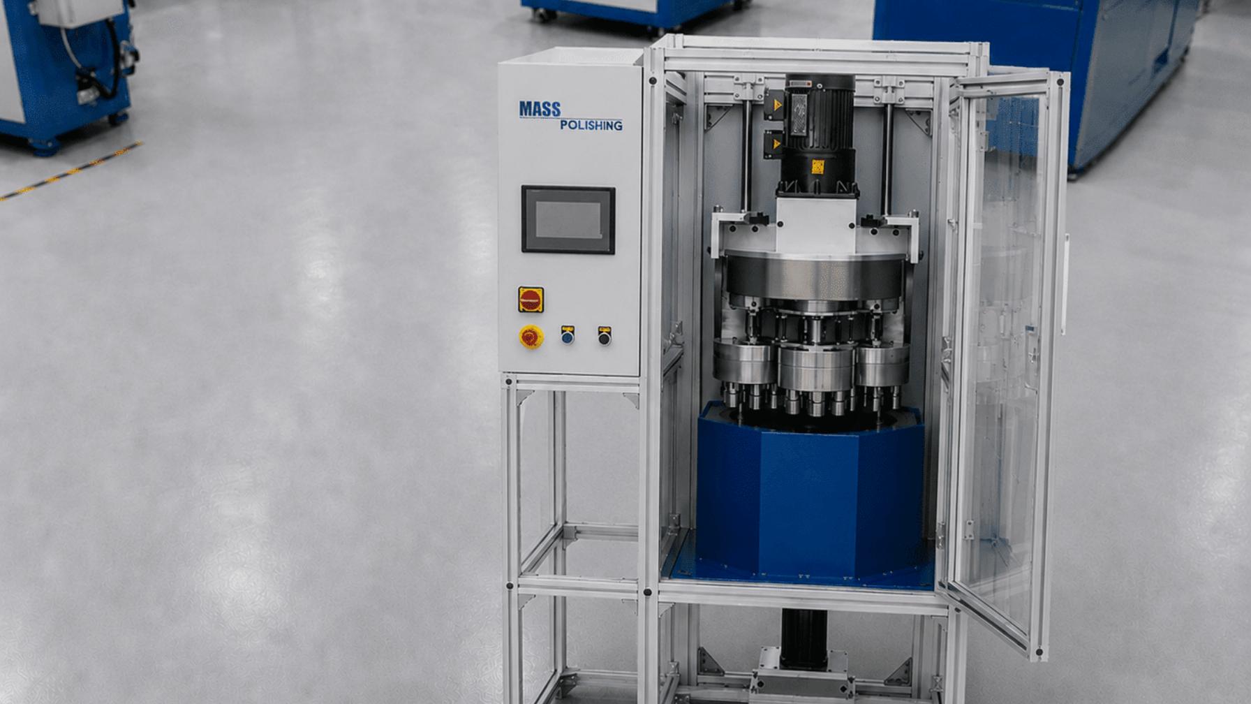
Four-barrel centrifugal machines are the usual tool for disc edge work because the barrels can be loaded and inspected individually. Mass Polishing builds the EB series in that configuration, from the EB 30 at 7.5 L per barrel and 0 to 185 rpm up to the EB 360 at 90 L per barrel and 0 to 90 rpm, with polyurethane-lined barrels and barrel and turret inching on the automatic models. Inching matters on discs: it lets the operator stop the turret with a barrel at the load position instead of waiting for a full revolution.
How Handling Sets the Limit on Casings and Large Parts
A casing is a large, thin, often circular part, and what happens around the process matters as much as the process.
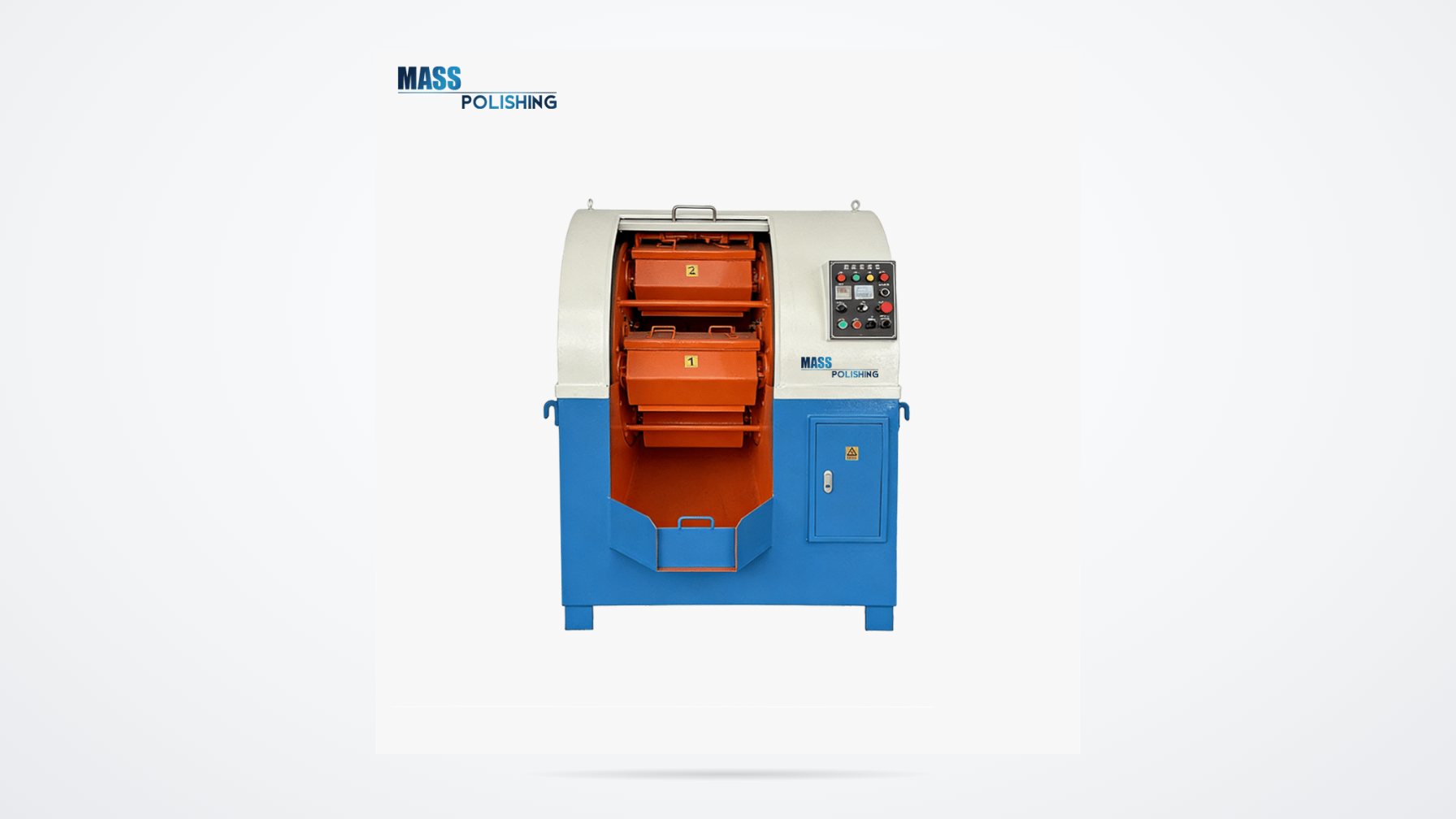
Trough machines handle long and large work, with capacities from 80 L on the smallest unit to several thousand litres on the largest, and dual imbalanced motors driving a U-shaped bowl. Large bowls cover the smaller casings. Both need low amplitude and good support to limit wall movement, and roundness or flatness should be checked after the cycle on any casing with a thin wall or a large unsupported span. Compartment dividers are worth using where part-on-part contact would mark a finished face.
Media retention is the failure mode that shows up later. Bores, blind holes and flange bolt holes collect media and compound, and a part that is dimensionally correct can still fail at coating because something remained in a cavity. The practical rules are to choose media larger than the holes that must stay clear, plug the ones that cannot be avoided, and inspect before the part leaves the area.
Rinse and dry belong in the specification, not at the end of the shift. A bore that stays wet is a corrosion site and a coating defect waiting to happen. Hot-air spin drying removes bulk water quickly; a unit with a 35 L basket, 1.8 kW of heating and a 50 to 70 °C working range covers typical small and medium casings, while large parts may need a second orientation so water does not sit in a pocket.
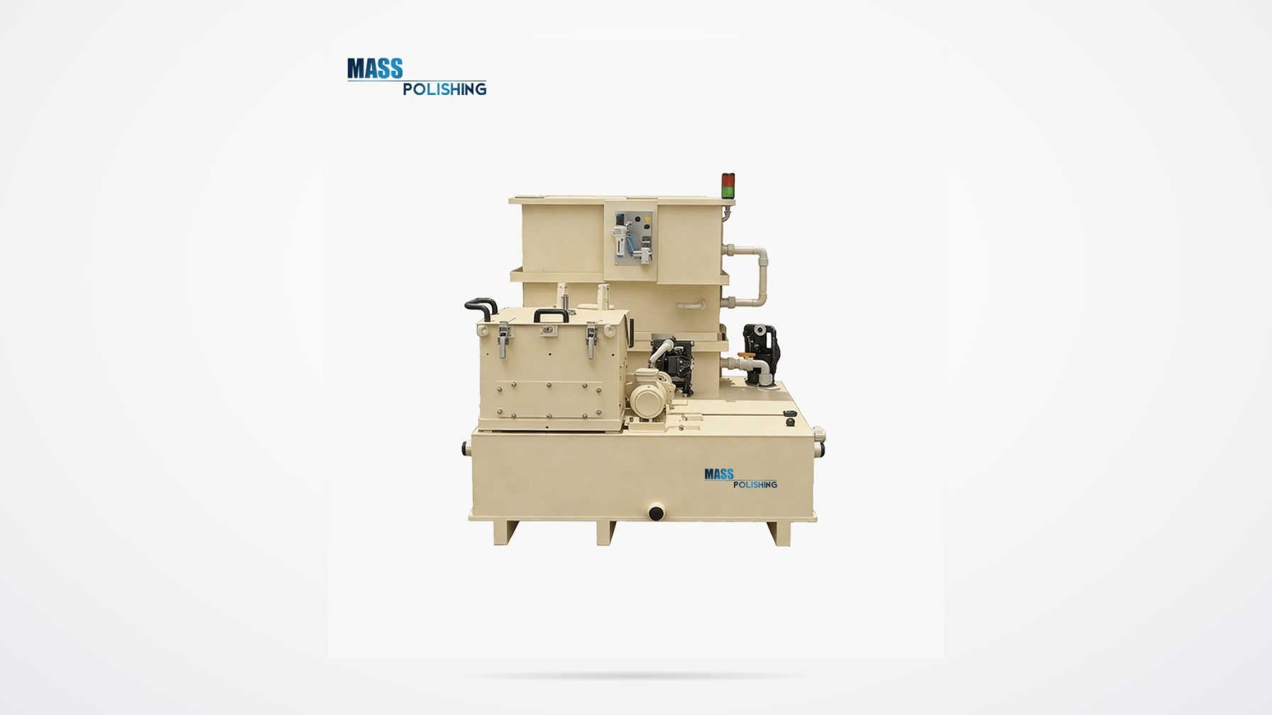
Effluent closes the same loop. Finishing with compound produces water carrying solids and oil, and discharging it untreated is both a compliance problem and a cost. A centrifugal water system separates solids at high speed and returns clarified water to the line; the published specification for the ST 1000 C lists a 3000 rpm bowl, up to 1000 L/h throughput and 95 to 98 percent separation efficiency, with the concentrated solids removed as waste.
– Spin Drying)
Media and Compound Choices for Titanium, Nickel Alloys and Aluminum
The media does the cutting, the compound controls the chemistry around it, and neither compensates for a wrong choice of the other.
| Media | Catalogue data | Where it fits on engine parts | What to watch |
|---|---|---|---|
| Ceramic P, deburr and polish | specific gravity 2.75, porcelain white | blade roots, disc edges and general edge break where a bright finish is wanted with the cut | dense media opens radii quickly on a thin trailing edge |
| Ceramic TC and MC, cutting | specific gravity 2.55 and 2.50 | heavier milling and turning burrs on casings, fittings and brackets | matte result, so it is a pre-finish step rather than the last one |
| Plastic V and LC | abrasive grit 1500 and 800 | aluminum parts and pre-coating preparation where embedment must stay low | low density cuts slowly on nickel alloys |
| Zirconia or stainless steel balls | 1 to 20 mm, and 2 to 10 mm | burnishing bores and faces to a bright, low-roughness surface | burnishing moves metal instead of removing it, so it cannot fix a burr |
| Porcelain pins | 1×3 up to 11×15 mm | recesses and small features that conventional media cannot reach | slow, and they need a compound that keeps them clean |
Alloy families do not share a media charge. Steel media leaves iron on titanium and aluminum, and that contamination becomes a corrosion site. Chloride-bearing chemistry on titanium is a stress corrosion risk. The working rule is dedicated media and dedicated compound per alloy family, with the machine cleaned between campaigns, and a compound whose data sheet states its pH and its intended metals rather than a generic “polishing liquid”. The catalogue values are a starting point: LC10 sits at pH 8.1 for general work and is not intended for brass, HM3 at 6.5 is mildly acidic, and HX0 at 2.2 is an acidic cleaner that needs a compatibility check before it touches titanium or aluminum.
Media size follows two limits at once. It must be larger than the holes that have to stay open and smaller than the smallest internal radius that has to be reached. Between those bounds, the media-to-parts ratio by volume and the compound concentration do more for consistency than a longer cycle.
Nickel superalloys work-harden quickly and respond differently from steel to the same media and compound. <Polishing Inconel Parts Tips and Techniques> covers practical points on finishing Inconel components.
How to Specify, Measure and Approve the Surface
A vague line on a purchase order is the most expensive item in a finishing job, because it gets interpreted twice and accepted once.
Reject this line: “Polish to Ra 0.4 and deburr all edges.”
Replace it with something a shop can actually plan against: name the surface and its function, the parameter with the cutoff and trace direction, the edge radius range and how it is measured, the position of the finishing step relative to peening and coating, and the authority that accepts the result. That replacement forces four decisions the original line left open, and each one changes media, fixture or cycle.
| Specification field | What to state | Why it changes the outcome |
|---|---|---|
| Surface and function | which surface the requirement applies to, and whether it is aerodynamic, fatigue-critical or a coating substrate | one roughness figure for a whole part cannot be met or inspected |
| Parameter and method | Ra or Rz per ISO 21920-2, with cutoff and trace direction | the same Ra at a different cutoff describes a different surface |
| Edge condition | radius range on named edges and the measurement method | “deburred” has no acceptance test |
| Sequence | whether finishing runs before or after peening and coating | the order preserves or removes the compressive layer |
| Starting condition | incoming roughness and the preceding machining route | media and cycle chosen for a different starting surface will miss |
| Acceptance record | who signs, what the report contains, how many parts form the first article | a trial nobody can repeat is not evidence |
A trial designed against those fields is short. Use a coupon of the same alloy and heat treatment, run it through the proposed cycle with the production media charge, and measure before and after by the agreed method. Then look at the surface under magnification for embedment and folded metal, because a good Ra can sit on top of a damaged layer. A coupon that only proves the machine can make metal shiny has proved nothing about the drawing.
Repeatability is the last check. When a finish drifts between batches, the cause is usually found in media condition, compound concentration or load pattern rather than in the machine, and the drift shows up first as a change in edge radius rather than in roughness.
When a finish shifts between batches, the cause is more often media condition, compound concentration or load than the machine itself. <Solutions to Common Problems of the Polishing Machine in the Polishing Process> covers common polishing problems and the causes behind them.
Send Parts Before You Commit to a Process
The cheapest way to settle a finishing question on engine hardware is to run the real parts. Send the component family, the alloy and its condition, the drawing or a marked print showing which surfaces and edges carry requirements, the position of the finishing step relative to shot peening and coating, the batch size, and the acceptance document you work to. Mass Polishing runs sample processing on production equipment and returns the parts with a measured report, so the cycle you approve has already been run on your geometry. Contact details and the current enquiry route are listed at www.masspolishing.com. Put the drawing reference in the first message and the trial can start without a second round of questions.
FAQ
Can blades and discs be finished in the same machine?
Sometimes the same machine type, almost never the same recipe. A four-barrel centrifugal machine can process small blades and small discs, but the media charge, compound, cycle time and load pattern differ because the geometric limit differs. The blade’s constraint is the trailing edge and the root contact face. The disc’s constraint is the slot root radius and the position of the step relative to shot peening. Sharing a machine is a scheduling decision. Sharing a media charge or a cycle recipe between the two is where geometry gets damaged.
What Ra can mass finishing achieve on a turbine blade?
No single figure means anything without conditions. The achievable roughness depends on the incoming surface, the alloy, the media, the compound and the cycle, and the reported number depends on the parameter, cutoff and trace direction. Two suppliers can quote the same Ra and describe different surfaces. The defensible route is a coupon of the same alloy and heat treatment, run through the proposed cycle and measured to the agreed method before and after, with the report stating cutoff and direction. A catalogue claim cannot be checked against your part.
Does polishing after shot peening reduce fatigue life?
It can. Peening works by leaving a compressive layer at the surface, and a mechanical finishing operation afterwards removes part of that layer. How much matters depends on stock removal and on the local geometry. When a drawing calls for finishing after peening, the engineering authority sets the limit and the verification method, and the holder of the peening approval confirms what is still acceptable. Running a polish after peening without that approval turns a designed surface condition into an uncontrolled one.
What should I send for a finishing trial on aerospace parts?
Send the alloy and its condition, the drawing or a marked print showing which surfaces and edges carry requirements, the sequence relative to peening and coating, the batch quantity, and the acceptance document you work to. Add the starting roughness and how it was measured. With that, a trial can be designed against the real constraint instead of a generic polish. Without it, the result may look right and still fail first article, because the trial answered a different question from the one on the drawing.
References
[1] SAE International, “AS9100D Quality management systems – Aerospace – Requirements,” SAE International, 2016.
[2] Performance Review Institute, “Nadcap accreditation program,” PRI.
[3] ISO, “ISO 21920-2:2021 Geometrical product specifications (GPS) – Surface texture: Profile – Part 2: Terms, definitions and surface texture parameters,” ISO, 2021.
[4] SAE International, “AMS 2430 Shot peening, automatic,” SAE International.
If you’re interested, check out these related articles:
Chain Manufacturers
Technical Operating Procedures for Vibrating Mills